[Estratto dal
sito: http://hissa.nist.gov]
2 Cyclomatic Complexity
Cyclomatic complexity [MCCABE1]
measures the amount of decision logic in a single software module. It
is used for two related purposes in the structured testing methodology.
First, it gives the number of recommended tests for software. Second,
it is used during all phases of the software lifecycle, beginning with
design, to keep software reliable, testable, and manageable. Cyclomatic
complexity is based entirely on the structure of software's control
flow graph.
2.1 Control flow graphs
Control flow graphs describe the logic structure of software modules. A
module corresponds to a single function or subroutine in typical
languages, has a single entry and exit point, and is able to be used as
a design component via a call/return mechanism. This document uses C as
the language for examples, and in C a module is a function. Each flow
graph consists of nodes and edges. The nodes represent computational
statements or expressions, and the edges represent transfer of control
between nodes.
Each possible execution path of a software module has a corresponding
path from the entry to the exit node of the module's control flow
graph. This correspondence is the foundation for the structured testing
methodology.
As an example, consider the C function in Figure 2-1, which implements
Euclid's algorithm for finding greatest common divisors. The nodes are
numbered A0 through A13. The control flow graph is shown in Figure 2-2,
in which each node is numbered 0 through 13 and edges are shown by
lines connecting the nodes. Node 1 thus represents the decision of the
"if" statement with the true outcome at node 2 and the false outcome at
the collection node 5. The decision of the "while" loop is represented
by node 7, and the upward flow of control to the next iteration is
shown by the dashed line from node 10 to node 7. Figure 2-3 shows the
path resulting when the module is executed with parameters 4 and 2, as
in "euclid(4,2)." Execution begins at node 0, the beginning of the
module, and proceeds to node 1, the decision node for the "if"
statement. Since the test at node 1 is false, execution transfers
directly to node 5, the collection node of the "if" statement, and
proceeds to node 6. At node 6, the value of "r" is calculated to be 0,
and execution proceeds to node 7, the decision node for the "while"
statement. Since the test at node 7 is false, execution transfers out
of the loop directly to node 11, then proceeds to node 12, returning
the result of 2. The actual return is modeled by execution proceeding
to node 13, the module exit node.
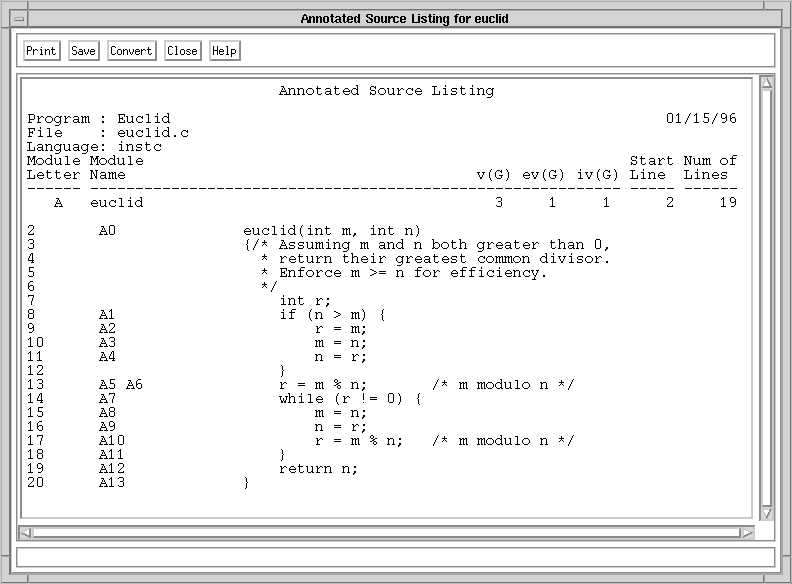
Figure 2-1. Annotated source listing for module "euclid."
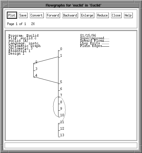
Figure 2-2. Control flow graph for module "euclid."
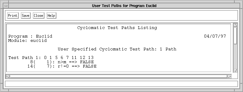
Figure 2-3. A test path through module "euclid."
2.2 Definition of cyclomatic complexity, v(G)
Cyclomatic complexity is defined for each module to be e - n + 2, where
e and n are the number of edges and nodes in the control flow graph,
respectively. Thus, for the Euclid's algorithm example in section 2.1,
the complexity is 3 (15 edges minus 14 nodes plus 2). Cyclomatic
complexity is also known as v(G), where v refers to the cyclomatic
number in graph theory and G indicates that the complexity is a
function of the graph.
The word "cyclomatic" comes from the number of fundamental (or basic)
cycles in connected, undirected graphs [BERGE].
More importantly, it also gives the number of independent paths through
strongly connected directed graphs. A strongly connected graph is one
in which each node can be reached from any other node by following
directed edges in the graph. The cyclomatic number in graph theory is
defined as e - n + 1. Program control flow graphs are not strongly
connected, but they become strongly connected when a "virtual edge" is
added connecting the exit node to the entry node. The cyclomatic
complexity definition for program control flow graphs is derived from
the cyclomatic number formula by simply adding one to represent the
contribution of the virtual edge. This definition makes the cyclomatic
complexity equal the number of independent paths through the standard
control flow graph model, and avoids explicit mention of the virtual
edge.
Figure 2-4 shows the control flow graph of Figure 2-2 with the virtual
edge added as a dashed line. This virtual edge is not just a
mathematical convenience. Intuitively, it represents the control flow
through the rest of the program in which the module is used. It is
possible to calculate the amount of (virtual) control flow through the
virtual edge by using the conservation of flow equations at the entry
and exit nodes, showing it to be the number of times that the module
has been executed. For any individual path through the module, this
amount of flow is exactly one. Although the virtual edge will not be
mentioned again in this document, note that since its flow can be
calculated as a linear combination of the flow through the real edges,
its presence or absence makes no difference in determining the number
of linearly independent paths through the module.
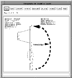
Figure 2-4. Control flow graph with virtual edge.
2.3 Characterization of v(G) using a basis set of control flow paths
Cyclomatic complexity can be characterized as the number of elements of
a basis set of control flow paths through the module. Some familiarity
with linear algebra is required to follow the details, but the point is
that cyclomatic complexity is precisely the minimum number of paths
that can, in (linear) combination, generate all possible paths through
the module. To see this, consider the following mathematical model,
which gives a vector space corresponding to each flow graph.
Each path has an associated row vector, with the elements corresponding
to edges in the flow graph. The value of each element is the number of
times the edge is traversed by the path. Consider the path described in
Figure 2-3 through the graph in Figure 2-2. Since there are 15 edges in
the graph, the vector has 15 elements. Seven of the edges are traversed
exactly once as part of the path, so those elements have value 1. The
other eight edges were not traversed as part of the path, so they have
value 0.
Considering a set of several paths gives a matrix in which the columns
correspond to edges and the rows correspond to paths. From linear
algebra, it is known that each matrix has a unique rank (number of
linearly independent rows) that is less than or equal to the number of
columns. This means that no matter how many of the (potentially
infinite) number of possible paths are added to the matrix, the rank
can never exceed the number of edges in the graph. In fact, the maximum
value of this rank is exactly the cyclomatic complexity of the graph. A
minimal set of vectors (paths) with maximum rank is known as a basis,
and a basis can also be described as a linearly independent set of
vectors that generate all vectors in the space by linear combination.
This means that the cyclomatic complexity is the number of paths in any
independent set of paths that generate all possible paths by linear
combination.
Given any set of paths, it is possible to determine the rank by doing
Gaussian Elimination on the associated matrix. The rank is the number
of non-zero rows once elimination is complete. If no rows are driven to
zero during elimination, the original paths are linearly independent.
If the rank equals the cyclomatic complexity, the original set of paths
generate all paths by linear combination. If both conditions hold, the
original set of paths are a basis for the flow graph.
There are a few important points to note about the linear algebra of
control flow paths. First, although every path has a corresponding
vector, not every vector has a corresponding path. This is obvious, for
example, for a vector that has a zero value for all elements
corresponding to edges out of the module entry node but has a nonzero
value for any other element cannot correspond to any path. Slightly
less obvious, but also true, is that linear combinations of vectors
that correspond to actual paths may be vectors that do not correspond
to actual paths. This follows from the non-obvious fact (shown in
section 6) that it is always possible to construct a basis consisting
of vectors that correspond to actual paths, so any vector can be
generated from vectors corresponding to actual paths. This means that
one can not just find a basis set of vectors by algebraic methods and
expect them to correspond to paths-one must use a path-oriented
technique such as that of section 6 to get a basis set of paths.
Finally, there are a potentially infinite number of basis sets of paths
for a given module. Each basis set has the same number of paths in it
(the cyclomatic complexity), but there is no limit to the number of
different sets of basis paths. For example, it is possible to start
with any path and construct a basis that contains it, as shown in
section 6.3.
The details of the theory behind cyclomatic complexity are too
mathematically complicated to be used directly during software
development. However, the good news is that this mathematical insight
yields an effective operational testing method in which a concrete
basis set of paths is tested: structured testing.
2.4 Example of v(G) and basis paths
Figure 2-5 shows the control flow graph for module "euclid" with the
fifteen edges numbered 0 to 14 along with the fourteen nodes numbered 0
to 13. Since the cyclomatic complexity is 3 (15 - 14 + 2), there is a
basis set of three paths. One such basis set consists of paths B1
through B3, shown in Figure 2-6.
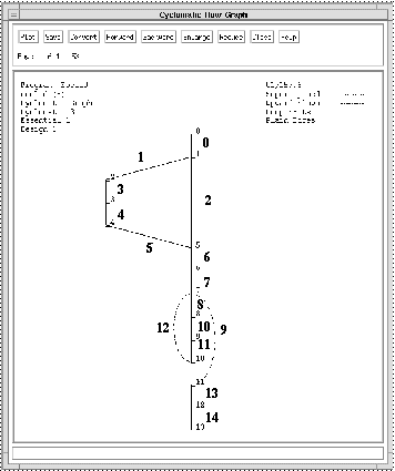
Figure 2-5. Control flow graph with edges numbered.
Module: euclid

			Basis Test Paths: 3 Paths

Test Path B1: 0 1 5 6 7 11 12 13

	8(    1): n>m ==> FALSE

	14(    7): r!=0 ==> FALSE

Test Path B2: 0 1 2 3 4 5 6 7 11 12 13

	8(    1): n>m ==> TRUE

	14(    7): r!=0 ==> FALSE

Test Path B3: 0 1 5 6 7 8 9 10 7 11 12 13

	8(    1): n>m ==> FALSE

	14(    7): r!=0 ==> TRUE

	14(    7): r!=0 ==> FALSE
Figure 2-6. A basis set of paths, B1 through B3.
Any arbitrary path can be expressed as a linear
combination of the
basis paths B1 through B3. For example, the path P shown in Figure 2-7
is equal to B2 - 2 * B1 + 2 * B3.
Module: euclid

			User Specified Path: 1 Path

Test Path P: 0 1 2 3 4 5 6 7 8 9 10 7 8 9 10 7 11 12 13

	8(    1): n>m ==> TRUE

	14(    7): r!=0 ==> TRUE

	14(    7): r!=0 ==> TRUE

	14(    7): r!=0 ==> FALSE
Figure 2-7. Path P.
To see this, examine Figure 2-8, which shows the
number of times each edge is executed along each path.
Figure 2-8. Matrix of edge incidence for basis paths B1-B3 and other
path P.
One interesting property of basis sets is that
every edge of a flow
graph is traversed by at least one path in every basis set. Put another
way, executing a basis set of paths will always cover every control
branch in the module. This means that to cover all edges never requires
more than the cyclomatic complexity number of paths. However, executing
a basis set just to cover all edges is overkill. Covering all edges can
usually be accomplished with fewer paths. In this example, paths B2 and
B3 cover all edges without path B1. The relationship between basis
paths and edge coverage is discussed further in section 5.
Note that apart from forming a basis together, there is nothing special
about paths B1 through B3. Path P in combination with any two of the
paths B1 through B3 would also form a basis. The fact that there are
many sets of basis paths through most programs is important for
testing, since it means it is possible to have considerable freedom in
selecting a basis set of paths to test.
2.5 Limiting cyclomatic complexity to 10
There are many good reasons to limit cyclomatic complexity. Overly
complex modules are more prone to error, are harder to understand, are
harder to test, and are harder to modify. Deliberately limiting
complexity at all stages of software development, for example as a
departmental standard, helps avoid the pitfalls associated with high
complexity software. Many organizations have successfully implemented
complexity limits as part of their software programs. The precise
number to use as a limit, however, remains somewhat controversial. The
original limit of 10 as proposed by McCabe has significant supporting
evidence, but limits as high as 15 have been used successfully as well.
Limits over 10 should be reserved for projects that have several
operational advantages over typical projects, for example experienced
staff, formal design, a modern programming language, structured
programming, code walkthroughs, and a comprehensive test plan. In other
words, an organization can pick a complexity limit greater than 10, but
only if it is sure it knows what it is doing and is willing to devote
the additional testing effort required by more complex modules.
Somewhat more interesting than the exact complexity limit are the
exceptions to that limit. For example, McCabe originally recommended
exempting modules consisting of single multiway decision ("switch" or
"case") statements from the complexity limit. The multiway decision
issue has been interpreted in many ways over the years, sometimes with
disastrous results. Some naive developers wondered whether, since
multiway decisions qualify for exemption from the complexity limit, the
complexity measure should just be altered to ignore them. The result
would be that modules containing several multiway decisions would not
be identified as overly complex. One developer started reporting a
"modified" complexity in which cyclomatic complexity was divided by the
number of multiway decision branches. The stated intent of this metric
was that multiway decisions would be treated uniformly by having them
contribute the average value of each case branch. The actual result was
that the developer could take a module with complexity 90 and reduce it
to "modified" complexity 10 simply by adding a ten-branch multiway
decision statement to it that did nothing.
Consideration of the intent behind complexity limitation can keep
standards policy on track. There are two main facets of complexity to
consider: the number of tests and everything else (reliability,
maintainability, understandability, etc.). Cyclomatic complexity gives
the number of tests, which for a multiway decision statement is the
number of decision branches. Any attempt to modify the complexity
measure to have a smaller value for multiway decisions will result in a
number of tests that cannot even exercise each branch, and will hence
be inadequate for testing purposes. However, the pure number of tests,
while important to measure and control, is not a major factor to
consider when limiting complexity. Note that testing effort is much
more than just the number of tests, since that is multiplied by the
effort to construct each individual test, bringing in the other facet
of complexity. It is this correlation of complexity with reliability,
maintainability, and understandability that primarily drives the
process to limit complexity.
Complexity limitation affects the allocation of code among individual
software modules, limiting the amount of code in any one module, and
thus tending to create more modules for the same application. Other
than complexity limitation, the usual factors to consider when
allocating code among modules are the cohesion and coupling principles
of structured design: the ideal module performs a single conceptual
function, and does so in a self-contained manner without interacting
with other modules except to use them as subroutines. Complexity
limitation attempts to quantify an "except where doing so would render
a module too complex to understand, test, or maintain" clause to the
structured design principles. This rationale provides an effective
framework for considering exceptions to a given complexity limit.
Rewriting a single multiway decision to cross a module boundary is a
clear violation of structured design. Additionally, although a module
consisting of a single multiway decision may require many tests, each
test should be easy to construct and execute. Each decision branch can
be understood and maintained in isolation, so the module is likely to
be reliable and maintainable. Therefore, it is reasonable to exempt
modules consisting of a single multiway decision statement from a
complexity limit. Note that if the branches of the decision statement
contain complexity themselves, the rationale and thus the exemption
does not automatically apply. However, if all branches have very low
complexity code in them, it may well apply. Although constructing
"modified" complexity measures is not recommended, considering the maximum
complexity of each multiway decision branch is likely to be much more
useful than the average.
At this point it should be clear that the multiway decision statement
exemption is not a bizarre anomaly in the complexity measure but rather
the consequence of a reasoning process that seeks a balance between the
complexity limit, the principles of structured design, and the
fundamental properties of software that the complexity limit is
intended to control. This process should serve as a model for assessing
proposed violations of the standard complexity limit. For developers
with a solid understanding of both the mechanics and the intent of
complexity limitation, the most effective policy is: "For each module,
either limit cyclomatic complexity to 10 (as discussed earlier, an
organization can substitute a similar number), or provide a written
explanation of why the limit was exceeded."
