3. Toy Examples
In this tutorial, we discuss a modeling example that addresses issues of distribution added on top of the original requirements specified in a well-known case study which has come to be known within the project as the "Toy Example" [Les06], to cover as broad a spectrum as possible of the use of the HRT-UML/RCM methodology.
Statement of the Problem
Following the definition given in [Les06],
the POS (Position store) is a
data resource shared by two processes: GNC
(Guidance, Navigation and Control) and TMTC
(Telecommand/Telemetry):
- TMTC either writes
to POS the data values uploaded from ground by a dedicated telecommand
(TC in the sequel) or sends a "BOOST_ORDER" command to the PRO (Propulsion Manager) component.
- GNC
performs a feedback-control loop on POS, by first reading the current
value, computing any necessary adjustments and then updating the
initial value accordingly.
- PRO (Propulsion manager) periodically executes its default operation unless it receives the "BOOST_ORDER" command, in which case PRO executes the "BOOST_ORDER" operation once, in place of the default one and then resumes nominal execution.
In the regard of the potential interaction between the two distinct update operations on POS, the problem specification stipulates that "If TC [command] occurs when GNC is active, the update of POS has to be delayed [i.e., deferred] until the termination of GNC[1]". To meet this requirement, the system must guarantee transactional access (with atomicity, consistency and isolation: "ACI" properties) to POS specifically for use by GNC. The difference between mutually exclusive and transactional access is described in detail in appendix 1.
Transactional access implies mutual exclusion access, but the converse does not hold.
The Partitioned Toy Example
As shown in figure 3.1, for the purposes of this discussion, the Toy Example is deployed on one computational node and three logical partitions residing on it. This configuration enables us to illustrate a broader spectrum of issues in the generation of the PSM views of the system.
- Partition P1: POS and GNC
- Partition P2: TMTC
- Partition P3: PRO
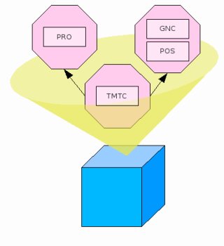
Figure 3.1: The Toy Example deployed on processor and three partitions
The Distributed Toy Example
As shown in figure 3.2, the physical graph (that is, the system interconnect) on which the Toy Example is deployed includes three distinct computational nodes. In keeping with the ASSERT assumptions, the network interconnect is point-to-point. We assume that one distinct instance of logical partition P3 (which includes one instance of PRO process) resides on each of the three physical nodes. This configuration allows us to illustrate issues of interest in the modeling of the PIM views.
Figure 3.2: Computational nodes and their
physical point-to-point interconnect
(Legend: The numbers that tag the interconnection links between nodes
denote the maximum bandwidth capacity of the relevant link expressed in
terms of a configurable predefined unit.)