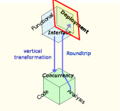
Figure 6.1: Deployment
6. The Deployment View
The designer uses the Deployment View to specify the physical architecture of the system target, to command the mapping between that and the logical architecture of the system and to assess the size, time and communication performance of the assignment.
The unit of allocation on a physical computation node is the logical partition, which is a user-defined aggregate of APLC. A single physical node however may host multiple logical partitions. A partition is a fault containment region: the APLC within a partition are isolated in space and time from all the other partitions in the system. (Cf. Figure 6.4.)
In the Deployment View, we consider partitions as "black-boxes" whereas in the weaving process we consider partitions as "white-boxes" and consequently treat their software contents as APLC. In the black-box interpretation of the Deployment View instead we are only interested in a specific attributes of partitions, for example memory size bounds and criticality level. A list of some of the attributes of a partition follows.
- min priority
- The minimum priority assignable to a thread within this partition. This is a derived attribute.
- max priority
- The maximum priority assignable to a thread within this partition. This is an automatically derived information.
- criticality
- A human-readable value which drives the derivation of the min and max priority values. Higher criticality generally translates into higher priority.
- criticality sub-order
- Whenever more partitions are modeled with the same criticality value this attribute allows to order them nevertheless.
- storage budget
- The amount of memory this partition is expected to require.
- time budget
- The amount of computational time per time unit this partition is expected to require.
- effective time budget
- The amount of computational time per time unit this partition actually requires.
- local scheduling policy
- the policy used to schedule threads within this partition. Presently, only Fixed-Priority Preemptive scheduling is available.
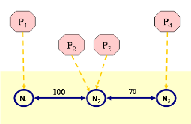
Figure 6.2 shows four partitions: P1, P2, P3, P4 and their assignment to three physical nodes: N1, N2, N3.

Figure 6.2: Partitions deployed on a physical graph
The table below reports the values of some attributes of some logical and physical components of this Deployment View.
|
|
|
Table 6.1: Attributes setting on physical nodes, interconnections and logical partitions
Once partitions are assigned to nodes, the HRT-UML/RCM tool automatically checks whether individual nodes have sufficient memory capacity for hosting the partitions to be deployed on them. For example, this check on node N2 would assess whether the following condition holds and warn the designer in case it did not.
In addition to checking the memory required by a partition against the memory available on the host node, the HRT-UML/RCM tool checks whether the physical communication channels provide enough bandwidth to support the communication between APLC deployed in different nodes. Whenever the amount of data exchanged between two nodes exceeds the available bandwidth, as specified in the Deployment View, a warning is raised to the user.
MN2 ≥ MP2 + MP3
At present the tool does not support the capture of the actual memory size of logical partitions, the relevant values must be therefore input by the designer. The incorporation of this feature is currently in progress.